
Build this app!
Download the example P&ID image here: https://drive.google.com/file/d/1g3QDJm37aBdK-yJJk3NOJLPBHMTu5am0/view?usp=sharing
Challenges of design engineers with complex multidisciplinary drawings
Throughout my career, I have faced multidisciplinary projects requiring me to combine my structural engineering skills with other domains. As an example, designing a pipe support structure meant first reading a P&ID (Piping and Instrumentation Diagram) to understand system operations and calculate loads. This process of learning symbols, layouts, and equipment took hours.
Similarly, when designing foundations for electrical substations, I had to carefully study single line diagrams. This involved estimating mechanical loads, checking fault currents, and aligning all details with structural requirements, another lengthy, manual task.
While reading P&IDs and single line diagrams is a daily activity for experienced mechanical and electrical engineers, it represents a significant learning curve for new team members. During onboarding, senior engineers often dedicate considerable time to teaching how to interpret these schematics, and the associated back-and-forth can slow overall progress. Furthermore, even for seasoned professionals, thoroughly analyzing these drawings and checking for errors can be very time-consuming.
Getting key information from these drawings often takes a lot of time and requires close examination. Here are some things my colleagues and I usually try to understand:
For mechanical drawings (P&IDs):
- System process flow
- Identification of main components and their function
- Connectivity and material/energy flow paths
For electrical drawings (substation single line diagrams):
- Understanding Substation Configuration and Layout
- Identifying Electrical Equipment
- Determining the Function and Role of Each Equipment Item
Fortunately, AI opens up possibilitiesto speed up this process.
With the introduction of vision and multimodal LLMs, you can now easily integrate natural language processing and computer vision capabilities at once. This makes it possible to build tools that help engineers quickly go through engineering drawings. Furthermore, AI-powered platforms like VIKTOR make building and sharing these powerful LLM-powered tools easier than ever!
In the following sections, you will:
- Create a simplified AI engineering drawing analysis app with the VIKTOR App Builder using only a prompt.
- Explore the complete custom-built application, including how it uses LLMs, image analysis, chat, and visual annotations under the hood.
Build your own AI engineering drawing analysis app
With the VIKTOR App Builder, you can create an AI engineering drawing analysis app without any programming experience. You only need to describe the core components of the app: an upload field for the engineering drawing, an image view to display it, a multimodal vision model to analyze the image, and an LLM chat field where users can ask questions about the drawing.
To try it yourself, download the example engineering drawing below, open the VIKTOR App Builder, and paste the prompt into the prompt box. The App Builder will generate an app that uses an out-of-the-box multimodal LLM, so you can start analyzing engineering drawings without setting up your own API key.
Build this app!
Analyze engineering drawings with LLMs
Now that you have seen how the app can be created from a prompt, let’s look at how it works under the hood. We’ll start by explaining the main components of the application. The app is powered by two Large Language Models (LLMs).
First, we're using OpenAI’s GPT-4o Mini, a powerful reasoning model responsible for answering your questions about the engineering drawings. It handles most of the user’s queries based on the content of the uploaded image. In parallel, we use Google's Gemini 2.5 Pro to highlight specific elements in the image, leveraging its impressive image recognition capabilities. This combination forms the core of our interactive workflow.
VIKTOR comes into play to centralize everything in a user-friendly web app. It provides several input blocks that make this interaction seamless. First, the LLM Chat field manages the conversation history and renders both your questions and the LLM's responses in real time, ensuring a continuous and natural interaction.
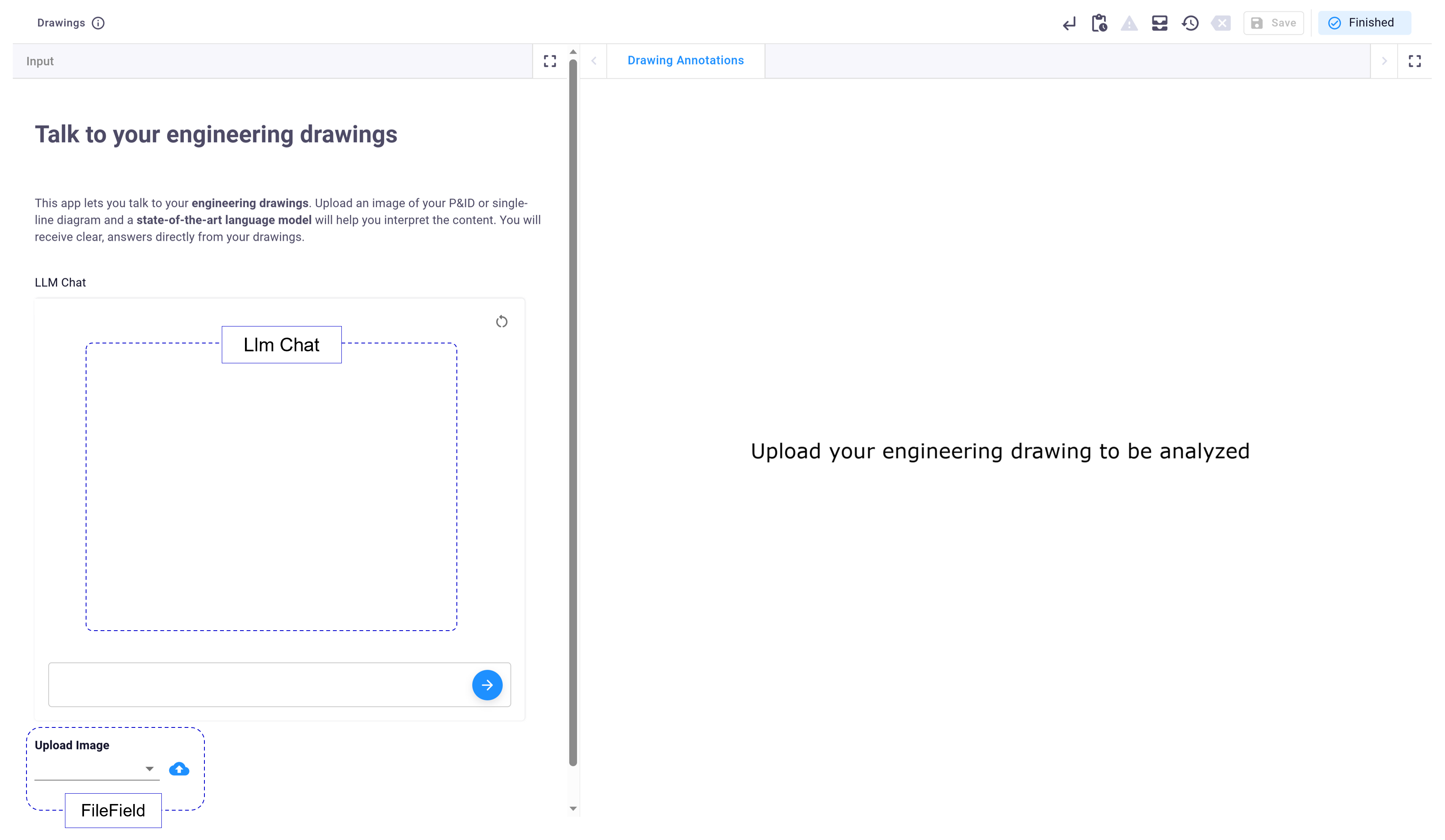
Next, the FileField allows you to easily upload images of your engineering drawings. These images are then sent to the LLMs for processing—GPT-4o Mini handles the image-based Q&A, while Gemini 2.5 Pro performs object detection to identify and highlight relevant elements.
The bounding boxes detected by Gemini are then plotted using a PlotlyView. This view updates dynamically whenever the LLM identifies a new object or section in the drawing that needs to be highlighted. This integration of two state-of-the-art LLMs delivers a rich user experience, combining visual feedback with an interactive conversation, almost like you're talking directly to your drawing!
Analyze P&ID Diagrams
Let's see the application in action. We will start by asking key questions needed to understand the content of the P&ID diagram.
System process flow
Understanding the overall system process flow is fundamental to interpreting any P&ID. A key initial question focuses on the system's main purpose and how materials or energy move through it. For example, you could use the following prompt for the AI: "What is the main purpose of the process shown, and how do the steam lines interact with the vessel to heat the incoming fluid?"
Identification of main components and their function
Next, focus on identifying main components like outlets, valves, pumps, and vessels, and understanding their specific functions. For example, you could use the following prompt for the AI: "How does the temperature-control loop (TT 100, TIC 100, TV 100) work together to keep the vessel at the target temperature?"
Connectivity and material/energy flow paths
Finally, dive deeper into how components are connected and trace material or energy flow paths. For instance, to understand the role of a valve or how a level transmitter interacts with a controller, you could use the following prompt for the AI: "What specific function does the orifice plate perform, and how do FT 101, FE 101, FIC 101, and FV 101 use its signal to regulate the outlet flow of heated fluid?"
The AI was able not only to understand the questions but also to provide answers specifically related to the drawings. This demonstrates how it can save significant time when reading and analyzing P&IDs.
Analyze substation single line diagrams
Since these models are trained on vast datasets, they can be used in other disciplines like electrical engineering. They are particularly handy for understanding single line diagrams, which are a cornerstone of electrical engineering projects.
Understanding substation configuration and layout
When reading a single line diagram, the first step is to identify the substation type (e.g., single bus, double bus) to understand its reliability and flexibility, and then to examine key equipment like circuit breakers and transformers. For instance, a good starting prompt for the AI would be: "What is the configuration of the substation? Only base your answer on the drawings. If any assumption is made in your answer or if there is uncertainty, state it."
Identifying electrical equipment
In my personal case (as a structural engineer), knowing which equipment is present in the single line diagram helps me understand how many foundations and steel structures are needed for the project. It also provides details about short-circuit loads or wire loads. Having all the elements listed in the chat field and also highlighted in the PlotlyView is a very useful feature.
Determining the function and role of each equipment item
With a general understanding of the single line diagram, the specific role of each component can be analyzed, especially those unique to each electrical system, by asking more detailed questions. For example, you could use the following prompt for the AI: "What is the role of the fault current limiters?"
Similar to the P&ID analysis, the AI effectively interpreted the substation single line diagrams, showcasing its versatility across different types of engineering drawings.
Limitations
It's important to acknowledge the current limitations. For instance, Gemini, while useful for simple annotations on drawings, doesn't yet match the performance of traditional object detection models like YOLO or custom-trained models, sometimes showing variability in labels and bounding box positions due to a lack of determinism.
Furthermore, remember that LLMs can make mistakes. It is always important to double-check their responses, especially for uncommon cases. Keeping a human in the loop for verification is crucial.
The good news is that these models can be fine-tuned. You can refine them with your own drawings and company data, which can lead to better results and fewer errors over time. Plus, these models are continuously improving.
Try the app (open source on GitHub)
Ready to integrate AI into your workflows? This app is open source on GitHub, so you can adjust it to fit your specific needs. You'll need API keys for both OpenAI and Google Gemini to run the application as described.
Making changes is simple. You can extend this to handle multiple images and multiple views at once, or even adapt it for structural, civil, mechanical, electronic, or other engineering applications.
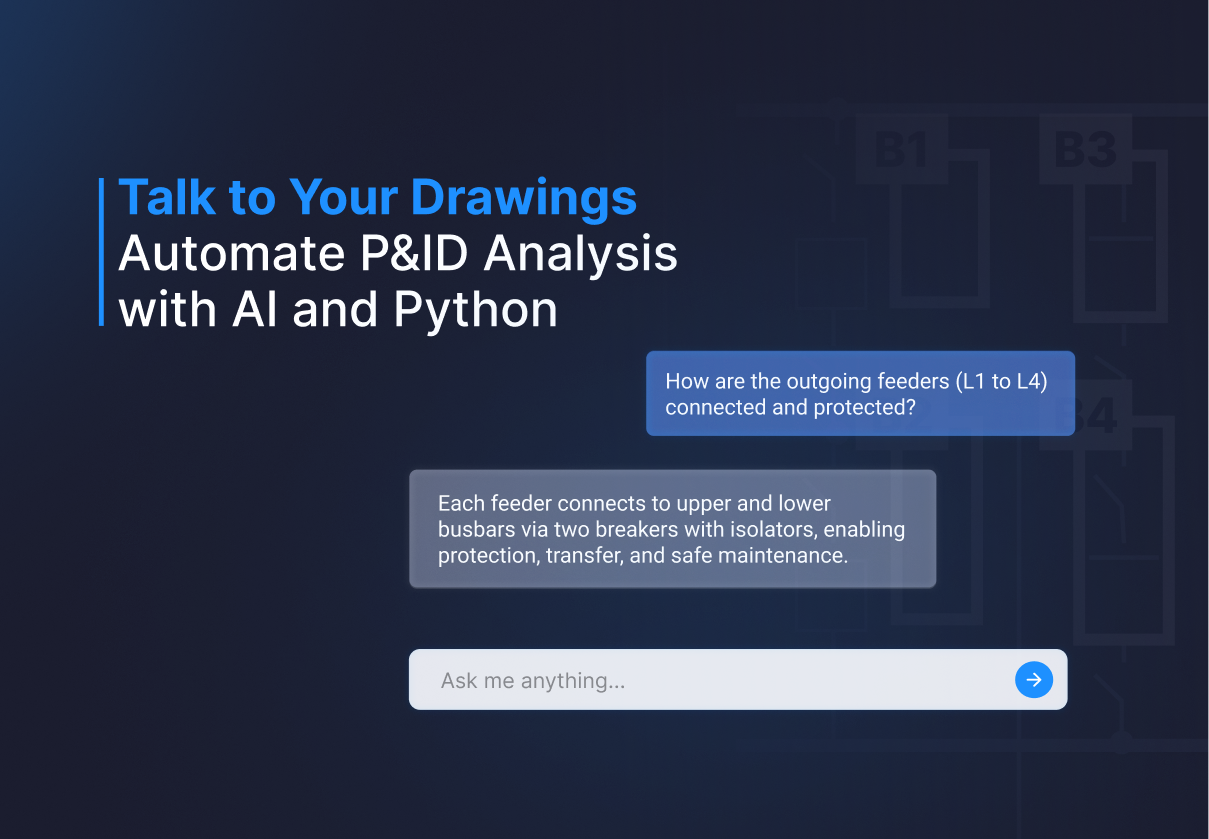
Bring AI into your workflows
In this blog, we covered how you can "talk" directly to your engineering drawings through AI. As shown, there's no magic behind this AI integration; it's easy to implement and is like having an engineering assistant that reads and understands the drawings for you.
Inspired by this application? This is just one example of how you can build AI-powered web apps with VIKTOR. For further inspiration, you can read our blog on how to create an app that lets you “talk” to your ETABS model results using the ChatField.
Developing AI-powered web apps for engineering has never been simpler. Join the growing community of engineers automating their tasks—create your own VIKTOR account now and enhance your engineering projects!
Start building apps for free