Download the White Paper and get INSPIRED
Learn about trends in digital transformation and how they affect the engineering and construction industry.
Increasing design efficiency
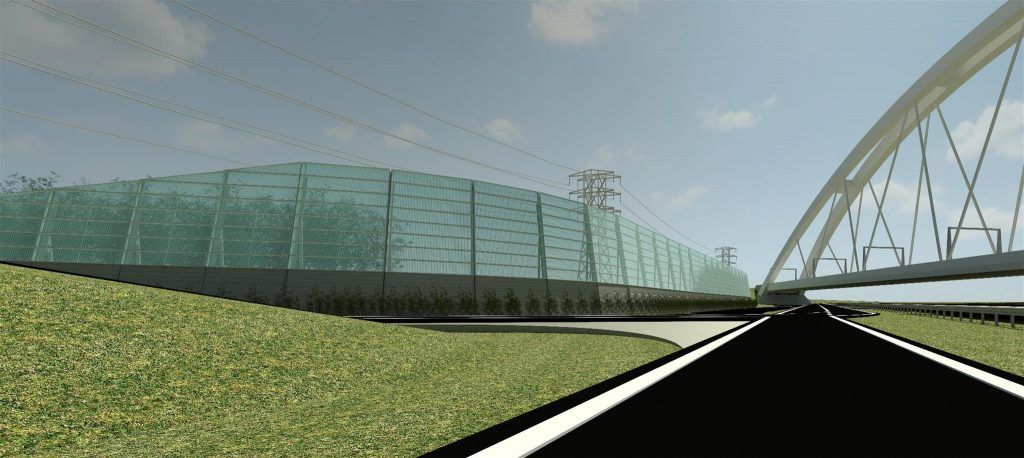
However, providing an adjusted design after each road or artwork change costs a lot of work. About two years ago, WTOP decided to investigate where most of the time was spent in the process of designing, and where this could be done more efficiently. This showed that in a number of these processes, many hours were spent on repetitive and unimaginative work. In addition, it turned out that arranging and creating a smooth line with these barriers is a complicated process and time-consuming. Jaap van de Werfhorst, owner of WTOP infra, decided that this process should be automated.
Automating the process
The work of manually placing elements along the road based on a maximum angular rotation and, if it turns out not to fit, to start this process all over again, had to find an alternative solution. WTOP infrastructure was in contact with VIKTOR to see how various processes could be better linked to each other, and the above mentioned problem was discussed with the question wheher using VIKTOR would be fruitful. At VIKTOR they came up with the proposal to do this with a self-written algorithm. Van de Werfhorst: “Initially, there was still uncertainty whether the algorithm could also handle complex projects. If it could carry out the 80% easiest projects, it would not be of much use to us, because it is precisely in the difficult 20% where the most profit lies.”
An application for complex projects
“After several brainstorming sessions, we were confident that the application could also handle complex projects,” explains Van de Werfhorst. In the application you can define your grid, the bounds of the design, the horizontal and vertical alignment, the maximum angular rotations between the elements, variables related to defining the angular rotations, other constraints such as cables and pipes, artworks, etc. and where you wants to apply your fitting elements. All these parts can be entered in both x, y and z directions. Based on all this input, the algorithm determines the optimal line of the noise barrier. In a visual representation, the application shows by means of colors whether the barrier can be made with the specified conditions. If it turns out that this does not work, the application indicates where the problems are, so that the conditions can be adjusted at those specific locations if desired. This can be done by increasing the angular rotation between the elements, which may then create elements that meet the requirements or by giving the barrier some more space by adjusting the bounds of the design. The great thing is that the program examines and calculates hundreds of thousands of possibilities within a few minutes. The application also generates a list of coordinates in x, y and z direction of the design. This list of coordinates is imported into Excel by WTOP infra, after which all elements that meet the requirements are generated by dynamo and placed in a 3D model. In addition, dynamo in combination with excel creates a quantity list with the main dimensions per element. As a result, the consequences of design choices are immediately visible in both a 3D model and quantities.
What can be gained?
Due to this extensive automation, instead of spending much work on unimaginative tasks, the time can now be spent on solving details and interfaces. The advantage is that various choices can be made clear at a detailed level quickly in the tender phase, which also makes it easier to estimate the risks. Since all parts and placements are generated from a single coordinate list, including the production drawings and layout drawings, it is also possible to act quickly during the design process and execution, and failure costs due to changes can be minimized.
Van de Werfhorst: “The step that we have taken together with VIKTOR ensures that we are at the beginning of a development that can be carried out much further by linking this to schedules, cost estimates, etc.” The application and links made with analysis- and drawing programs are useful not only for noise barriers, but also for everything in which prefabricated (3D) elements are placed on or along an alignment, which is currently also being implemented.


