Download the white paper and get INSPIRED
Learn how collaborative parametric design models allow you to work together for better solutions.
Dike design tool Wilma: a new, digital way of designing
The Wilma dike design tool, created on the VIKTOR platform, is a renewed design environment for the geotechnical consultant. The tool was developed by the Graaf Reinaldalliantie to be used on the Gorinchem-Waardenburg (GoWa) dike reinforcement project.
The innovation consists of the combination of cleverness and insights of the designer and the infinite computing power of the computer on the VIKTOR platform. For the Wilma tool, design software for the various design mechanisms (D-series and PLAXIS) is integrally linked and data is centrally managed in accordance with the BIM philosophy. Because of this, changes in starting points or other information can be made transparant very quickly, allowing the design to adapt quickly as well. This provides a certain flexibility in the design process that has proven itself to be very beneficial within this project.
A challenging reinforcement
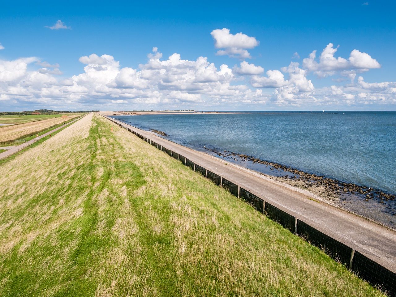
The Graaf Reinaldalliantie was established to strengthen the river dike between Gorinchem and Waardenburg. The alliance consists of the Water Board Rivierland and the contractor consortium ‘Waalensemble’ consisting of Heijmans, GMB and de Vries & van de Wiel. Royal HaskoningDHV is associated with the alliance as an advisory party as well.
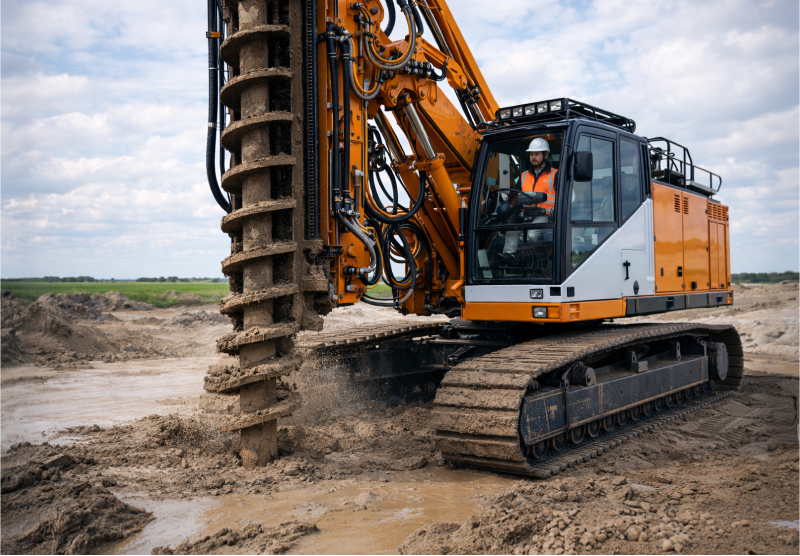
This dike improvement project is approximately 23 kilometers long and is particularly complex in terms of tasks related to reinforcement. Not least because of the highly heterogeneous soil structure, which was created in the past on the north side of the Waal by the many old river channels and fillings, the diversity of soil layers and the filling in at the site of old dike breaches. The dike body itself also varies in structure due to the construction of the dike over the centuries and the reinforcements and relocations of the past decades. In order for this dike section to meet current safety standards, several improvement measures are needed that, together with the built environment, the soil conditions, and the transition to undrained modeling, make it a very challenging project.
Taking initiative
In the tendering phase of the Gorinchem-Waardenburg dike reinforcement project, Waalensemble took the initiative to perform the design calculations in a smarter, more efficient way, based on the positive experiences from previous Heijmans projects (Wilhelminakanaal, Wintrack) where repetitive design issues in particular were efficiently automated. In these examples, design software (D-Series, SCIA, Excel) is linked by means of assumptions and existing equations, resulting in an automated process. This principle has been adopted by the Gorinchem-Waardenburg dike improvement project, further elaborated and further professionalised through the availability of the VIKTOR platform, among other things. The Viktor platform makes it possible to link design software in a much easier way and with extra functionality than was previously possible in the aforementioned Heijmans projects. During the project, the functionality of the dike design tool was expanded in various versions with settlement and failure mechanisms such as macro stability, piping and overtopping, which can be calculated simultaneously per cross section, for both embankments and dike relocations. An example of a schematic of a profile is shown in the picture below.
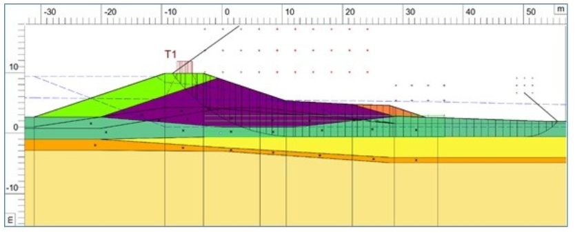
An example of a cross section schematized by Wilma with a crown displacement and inward embankment in a D-GeoStability calculation.
The first development
The first development motif arises from the request to support the designer in achieving a higher quality of the stability calculations. The application of the undrained CSSM model requires a schematisation with boundary tensions and a course of the effective tension due to changed water levels and previous loads. Within the functionality of the then available D-GeoStability version 18, this required a far-reaching division of the soil layers with additional stress calculations by the designer. The first version of Wilma has been developed to achieve an accurate calculation of the stresses and to develop an efficient method to include these results in the D-GeoStability model.
The second development
After a successful application of the first version, the second development started almost immediately. The functionality has been extended to centrally manage the input and output of the various design software. This is in line with the BIM method for quality assurance and version management. In a design analysis, the geotechnical properties per soil layer and the derived parameters that are determined by means of a calculation method, always originate from Wilma and are independent of other design calculations. The old and the new process diagram, where the parametric design tool is central, is shown here:

Traditional design process versus new design process with Wilma.
From this central position, Wilma compiles the input files and sends them to the existing design software, such as the D-series or Plaxis. The results from the design software are then collected and presented via the parametric design tool. By automating the data flow in the design process, the effort for the designer has shifted from drawing up calculation files to supervising the quality assurance of the calculations and assessing the results.

A new design methodology
The greatest gains, however, come from a different design method. The traditional design method is based on the manual input of cross sections by a consultant, which forces planning to make choices about how many cross sections can be calculated. In a complex project such as this dike improvement, this quickly means that major simplifications are needed to realise a design within time and money. One calculation that is normative for hundreds of meters of dike is common. As a result, the design is over-dimensioned, which in principle is not wrong from a safety point of view, but does lead to strict and heavy measures that affect the environment and are therefore not always desirable from stakeholders.
An automated way
A new automated way of calculating means that it will be possible to calculate a very large number of cross sections, instead of one standard profile. In theory, a transverse profile can be calculated with possible variants for each dike stretch where a different situation arises. This is shown schematically in figure 3, where each block represents a new situation.
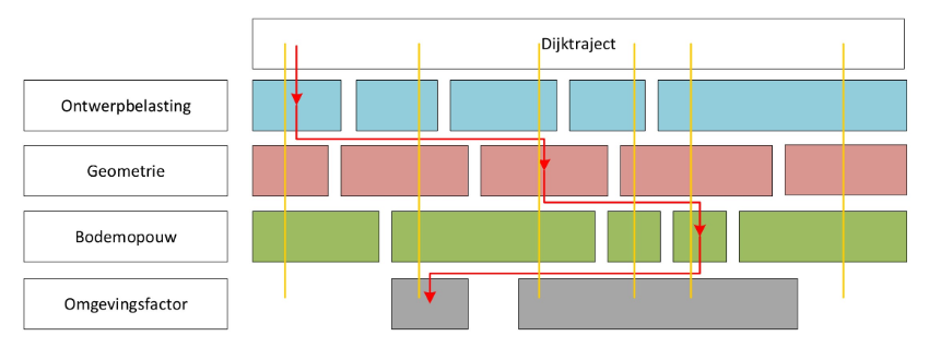
The schematic choice for a standard profile (red) or several representative profiles (yellow)
The ability to design a large number of profiles provides the following benefits:
- The consultant needs considerably less time to calculate cross sections, which means more time for interpreting and analysing results and translating them into the design. This leads to great efficiency.
- There is the possibility to perform sensitivity analyses in a simple manner with all kinds of starting points, so that a better insight is obtained which parameter influences the calculation result. This makes it possible to conduct targeted additional research quickly.
- The calculations were adapted and carried out very quickly. While changes in the traditional design process can have major consequences for the interfaces of the design, this is no longer a problem due to all the connections built up in Wilma. Adjustments to the design or starting points can now be directly calculated for the entire route.
Qualitatively better design
All this results in a qualitatively better design, whereby freedom is created in choosing a design solution based on the calculation results. It is therefore no longer necessary to funnel the output data in advance to compose a benchmark profile, because making the assessment is more extensive than designing an additional profile. In addition, the thinking for weighing up the various possible normative aspects is retained in the result of an additional design profile. The figure below shows this as an example through sketches and illustrations, in which the dike sections are the product of a normative cross section and the white line represents a possible design profile that, as is to be expected, more closely follows the soil structure found. Because the design profile of the white line has actually been calculated, it is possible to choose a more average design profile that fits better in the landscape. The robustness of the design is known at that time.
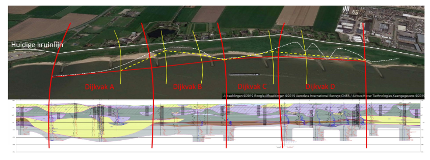
The division into dike sections with a schematic representation of the design assignment
Inclusion of additional soil research
An additional positive effect is that carrying out additional soil research now pays off because it can be processed more easily in the built-up subsurface model. With the traditional design method, additional soil investigation is often intended as a risk mitigation to verify the subsurface model. This advantage remains, however, with the design method with Wilma, the additional research is immediately included in the calculations and the design is adjusted.
Quality assurance
Processing results
Quality assurance of the design calculations is not formally included in Wilma. The role of the parametric design tool is to compile and start the calculations and to process the results. These design calculations are always performed with the original (and therefore validated) design software. For example, a stability calculation is performed in D-GeoStability, after which the files are also available, in such a way that it looks like a colleague has supplied the calculations. Each calculation is delivered separately from the tool and manually checked by the designer. This workflow of the calculation files also makes it possible to deliver and view the design without having Wilma.
Centralized storage
The quality assurance of the design calculations has deliberately been left with the designer. However, the parametric design tool makes it easier for the designer to perform the checks. Firstly, because the process of illustrating through schematics, calculating and checking is almost continuous because the lead time for a design calculation is next to nothing. In addition, Wilma can compile overviews of the required control points. All basic principles and relationships important for the design can be checked because the results are stored centrally and are available to everyone.
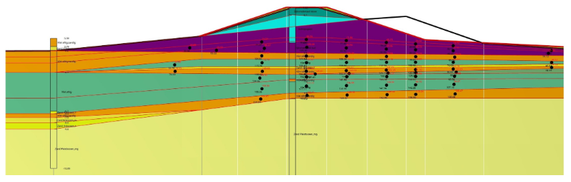
An example of a simple check is a graphical representation of the stresses in the soil layers or the assignment of the rise height to soil layers. Such a control screen is shown in figure 5. The calculated values are presented for each black-marked point in the design profile. The applied calculation values can be checked at a glance because the assumptions and equations have been consistently and unambiguously applied by Wilma on the basis of the predefined protocol. There are no quality differences due to the preparation of cross sections by several consultants.
Background testing
In order to properly verify Wilma’s work processes, various tests have been built into the Viktor platform during the development of the tool. This checks in the background whether the routines carried out by Wilma always run in accordance with the geotechnical specification. These tests roughly consist of three categories:
- Rules of thumb; the obvious design rules are checked. Because Wilma applies standard rules, contradictions can arise, as a result of which the schematization steps are correct in accordance with the “design rules”, but the schematization as a whole is geotechnically incorrect. An example of such a test is the descending height to the hinterland.
- Realistic modeling with fully elaborated schematics of calculations and links. When going through these tests, the routines must always give the same results.
- Edge cases with exceptional cases to test the routines of the schematisation. During these tests, unrealistic situations are presented from a geotechnical and hydraulic engineering point of view. This ensures that the routines and rules of thumb are robust and that new exceptions are noticed.
By continuously testing with both realistic modeling that is expected within the project, and with edge cases, the behavior of the tool becomes predictable, so that the quality control focuses on exceptions. These exceptions in turn complement the design routines. The systematic elaboration of these exceptions in a design rule results in a more substantiated design methodology and the percentage of exceptional cases is further reduced. This continuous development of the parametric design tool with the insertion of exceptional cases has resulted in the design capacity increasing quadratically. This increase is based on the difference between the number of design profiles per consultant in the exploration phase and the plan elaboration phase.
The next step
The tool is currently being further developed for more geotechnical functionalities and applications throughout the design process. The possible future expansion of the functionality of the tool can be sought in expanding the tool in the field of computing in the cloud, but also in adding IoT data from sensor technology in dikes. Both seem far away for now, but will sooner or later enrich the world of the civil industry.
See how you can develop your own parametric design tools.